 Skip to content
 Wire drawing is a metalworking process used to reduce the cross-section of a wire by pulling it through one or more dies. This process is essential for producing various metal wires, including those used in construction, electronics, jewelry, springs, and cables. The wire drawing process is usually performed at room temperature, classifying it as a cold working process, which enhances the mechanical properties of the wire.
This guide is intended for manufacturing professionals, engineers, and technical buyers seeking to understand the capabilities and selection criteria for wire drawing machines. Understanding wire drawing machines is crucial for anyone involved in wire production, as these machines are fundamental to creating products such as cables, fasteners, springs, and electronic components—each requiring different precision and properties.
This article explains what a wire drawing machine is, how it works, the different types available, and how to choose the right one for your needs. We will cover the following main topics:
- The working principles of wire drawing machines
- The major types of wire drawing machines and their configurations
- Key technical specifications and selection criteria
- Applications and importance across industries
- Operation, maintenance, and safety best practices
By the end of this guide, you will understand both the wire drawing process and how to select the right machine for your specific production requirements.
Key Takeaways
A wire drawing machine reduces rod or wire diameter by pulling it through one or more hardened dies, improving strength, surface finish, and dimensional accuracy for industrial use. This cold working process transforms a raw metal rod into a precisely sized wire suitable for everything from electrical conductors to structural cables.
- Machine classifications include single-block, multi-pass straight-line, pulley, wet (water tank), vertical, and bullblock types, each suited to specific wire diameters and materials ranging from fine copper to heavy steel bar.
- Modern drawing speeds for steel wire routinely reach between 3 m/s and 50 m/s, with fine wire lines exceeding 1,000 m/min on equipment built since around 2010.
- Critical selection parameters include inlet/finish diameter range, pulling force (up to 500,000 N for heavy bullblocks), and capstan size (typically 250–1,200 mm) to match your production and quality requirements.
- Diverse applications span cold heading wire, spring wire, cable production, and structural rope manufacturing, with the rest of this article comparing machine types, key technical specifications, and typical uses.
Sky Bluer Industries offers a comprehensive range of wire drawing machines designed to meet the diverse needs of modern manufacturing, combining advanced technology with reliable performance.
The Importance and Uses of Wire Drawing Machines
Wire drawing machines are essential for producing a wide variety of metal wires used in industries such as construction, electronics, jewelry, automotive, and telecommunications. The final products include cables, fasteners, springs, and electronic components, each requiring specific precision and material properties. Without wire drawing machines, it would be impossible to achieve the dimensional accuracy, surface finish, and mechanical strength needed for these critical applications. This article will help you understand both the wire drawing process and how to select the right machine for your needs, ensuring your production meets industry standards and application requirements.
What Is a Wire Drawing Machine?
A wire drawing machine is equipment that pulls a metal rod or wire through one or more hardened dies to reduce cross-section, increase length, and achieve tight diameter tolerances—often within ±0.01 mm for fine wire applications. Wire drawing is a metalworking process that relies on plastic deformation under tensile force, which elongates the wire while enhancing its mechanical properties through molecular alignment. The process is typically performed at room temperature, classifying it as a cold working process.
Dies are hardened inserts, often made from tungsten carbide or diamond, that shape the wire as it is drawn through. The capstan (or drawing block) is a rotating drum that grips and pulls the wire through the dies. The main machine types include straight-line, inverted vertical, multi-block, and wet machines, each serving different functions and wire sizes.
The wire drawing process is widely applied to carbon steel, stainless steel, copper, aluminum, and specialty alloys. These materials become products like electrical wiring conductors, springs, fasteners, nails, and cables used across construction, automotive, and electronics industries.
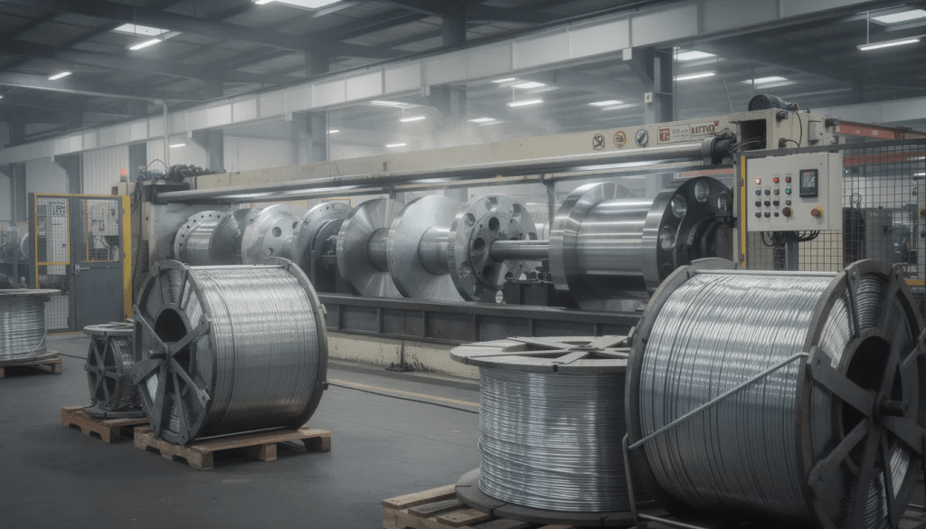
A typical industrial wire drawing machine includes several essential components:
- Payoff system – holds and feeds the inlet rod or wire coil with controlled tension
- Die box or cassette houses the tungsten carbide or diamond dies that reduce the diameter
- Capstan or drawing block – a rotating drum that grips and pulls the wire through each die
- Lubrication system – applies dry soap or wet emulsions to reduce friction and extend die life
- Drive motor and gearbox – provides the power and speed control for consistent operation
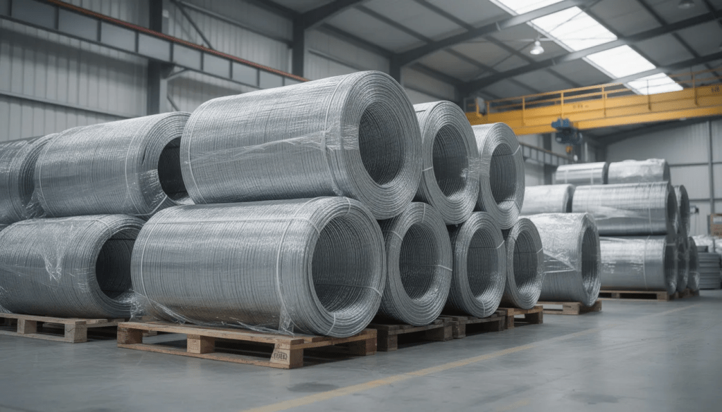
- Take-up coiler or spooler – winds the finished wire into neat, tensioned coils
Modern lines incorporate electronic speed control, load monitoring, and safety guarding to maintain consistent drawing speed and protect operators. PLC control systems managing multiple AC motors via frequency converters enable stepless speed adjustment with low failure rates.
Sky Bluer Industries’ wire drawing machines are equipped with state-of-the-art control systems and robust mechanical designs, ensuring optimal performance and durability in demanding industrial environments.
Next, we’ll explore how these machines operate in detail.
How Wire Drawing Machines Work
Understanding the fundamental mechanics of wire drawing helps you evaluate equipment options and optimize your production process. This section describes the basic wire drawing principle and how it translates into industrial machinery.
Preparation and Threading
- Preparation – Wire rod (typically 5.5–13.0 mm hot-rolled coil) is descaled through pickling to remove oxide layers, then the leading end is pointed to pass through the first die opening.
- Threading – The pointed wire is threaded through the die and gripped by the drawing block or capstan.
Drawing and Accumulation
- Drawing – The powered capstan rotates, creating a tensile force that continuously pulls the wire through the die, reducing the diameter while increasing the length. Since metal volume remains constant, a 10-20% diameter reduction per pass significantly elongates the wire.
- Accumulation – In multi-pass machines, the wire wraps around each capstan before entering the next smaller die, with each stage running at progressively higher speeds to accommodate the wire’s increasing length.
Take-up Process
- Take-up – The finished wire is wound onto a coiler that maintains constant tension synchronized with the final drawing speed.
Die Design and Arrangement
Dies are typically made from tungsten carbide for steel wire applications, offering excellent wear resistance at moderate cost. Diamond dies serve for very fine wire or high-volume production where extended life justifies the expense. Die approach angles usually range from 6° to 15°, with steeper angles suitable for soft metals and gentler angles reducing friction on harder materials.
Die arrangements fall into two main categories:
- Single-pass (single-block) – One die and one capstan handle limited reductions, often for skin-pass or finishing operations
- Multi-pass (straight-line or pulley) – Multiple dies and capstans in sequence enable rod breakdown from large inlet diameters to fine finished wire in one continuous operation.
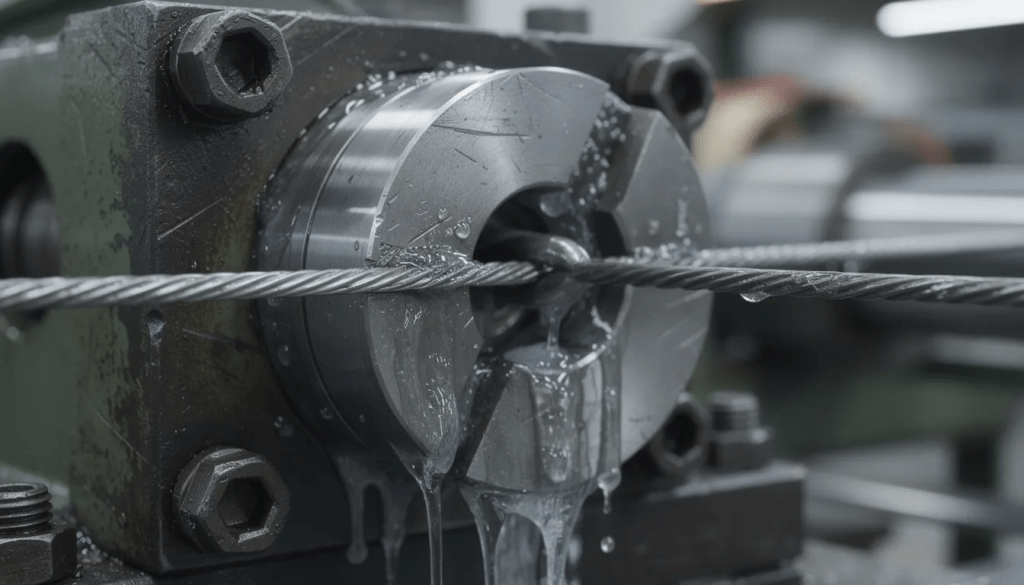
Lubrication Methods
Lubrication reduces friction, lowers die wear, and improves surface finish. Two primary methods apply:
- Dry drawing – Wire passes through soap boxes containing solid lubricant before each die. This approach is economical for medium and larger wires above 3.0 mm in diameter.
- Wet drawing – Wire runs through a water or emulsion-filled tank, providing intensive cooling and lubrication. This method is common for fine wire below about 3.0 mm diameter, where surface quality and die life are especially critical.
Single-Block vs. Continuous Multi-Block
- Single-block machines handle one die at modest speeds (around 6 m/s maximum) and are well-suited for skin-pass operations or limited diameter reductions on heavy wire.
- Continuous multi-block straight-line machines arrange 3 to 12 capstans in sequence, enabling high-speed production up to 40–50 m/s for fine and medium wire after appropriate heat treatment between passes.
If you are interested in the different types of wire payoff machines used in conjunction with these systems, there are various options to suit your production requirements.
The straight-line configuration eliminates traditional pulleys, providing better tension control between blocks, reduced slip, and consistent elongation throughout the drawing sequence.
With a clear understanding of the wire drawing process, let’s move on to the major types of wire drawing machines and their specific applications.
Major Types of Wire Drawing Machines
Wire drawing machines are classified by layout and application, with each design optimized for specific wire diameters, materials, and production requirements. The major categories include single block, straight-line, pulley, wet (water tank), vertical, inverted capstan, and bullblock/suspended block machines.
Sky Bluer Industries has developed a versatile portfolio of wire drawing machines covering these types, ensuring customers find the perfect match for their production goals.
The following table provides an overview of the main machine types, their typical inlet ranges, speeds, and best applications:
Table: Comparison of Major Wire Drawing Machine Types
| Machine Type | Typical Inlet Range | Typical Speed | Best For |
|---|---|---|---|
| Single-block | 0.7–17.0 mm | Up to 6 m/s | Skin-pass, finishing |
| Straight-line multi-block | 0.45–20.0 mm | Up to 50 m/s | Rod breakdown, high-speed production |
| Inverted capstan | 5.5–18.0 mm | 2.5–3.0 m/s | Heavy wire, high-force operations |
| Bullblock | 12–50 mm | 2.5–3.0 m/s | Heavy structural wire, bar |
| Pulley | 2–8 mm | Moderate | Medium wire, simple installations |
| Vertical | 8–40 mm | Low to moderate | Thick wire, space-constrained layouts |
| Wet (water tank) | 0.10–3.0 mm | High-quality wire drawing machines | Fine wire, critical surface finish |
The following subsections provide detailed specifications and typical applications for each machine type, with real-world capacity and performance examples to guide your selection.
Single-Block Wire Drawing Machines (Skin-Pass and Finishing)
Single-block wire drawing machines use one drawing capstan and one die set, making them ideal for light reductions, skin-pass drawing, or finishing operations on pre-drawn steel wire. These machines excel when you need to make final diameter adjustments or improve surface quality without major cross-sectional area reduction.
Typical application ranges:
- Wire sizes – Inlet diameters from about 0.7 mm up to 17.0 mm
- Reduction – Usually 5–15% diameter reduction per pass
- Materials – Low and high carbon steel, stainless steel, and specialty alloys
Machine size categories:
Table: Single-Block Machine Size Categories
| Wire Drawing Machine Categories | Capstan Diameter | Drive Power | Wet Drawing Machine | Max Speed |
|---|---|---|---|---|
| Small | ~500 mm | ~30 kW | ~10,000 N | ~6 m/s |
| Medium | ~700 mm | ~55 kW | ~30,000 N | ~6 m/s |
| Heavy | ~900 mm | ~110 kW | ~60,000 N | ~6 m/s |
Maximum drawing speeds for skin-pass machines remain modest (around 6 m/s) to preserve surface quality and dimensional accuracy on medium and large wire sizes. The single-die arrangement simplifies operation and maintenance while delivering the precise control needed for finishing operations where every pass matters.
Straight-Line Multi-Block Wire Drawing Machines
Straight-line drawing machines arrange multiple capstans in a line, each with its own die, eliminating traditional pulleys and enabling precise, high-speed rod breakdown and re-drawing. This configuration has become the industry standard for modern high-volume wire production.
Common applications:
- Processing low and high carbon steel rods with inlet diameters from roughly 0.45 mm up to about 20.0 mm
- Producing finish diameters down to 0.4–8.0 mm, depending on configuration
- Manufacturing wire for cold heading, spring production, welding electrodes, and cable construction
Table: Straight-Line Machine Specifications by Application
| Application | Inlet Range | Capstan Diameter | Drive Power | Pulling Force | Max Speed |
|---|---|---|---|---|---|
| Fine wire re-drawing | 0.45–3.0 mm | 250–400 mm | 15–22 kW | 6,000–15,000 N | 40–50 m/s |
| Medium wire | 1.0–10.0 mm | 400–630 mm | 30–75 kW | 20,000–45,000 N | 25–40 m/s |
| Rod breakdown | 5.5–20.0 mm | 500–900 mm | 90–160 kW | 50,000–90,000 N | 10–25 m/s |
Key advantages of online wire drawers:
- Better tension control between blocks through individual motor drives
- Reduced slip from precision capstan surface treatments
- Consistent elongation across all passes
- Compatibility with automatic coilers and inline coating or heat treatment systems
- Simplified threading compared to pulley systems
These machines handle the full spectrum from rod breakdown to fine wire production, making them suitable for operations requiring versatility and high throughput.
Inverted Capstan and Suspended Block Machines
Inverted capstan and suspended block machines handle heavy wire and bar with the capstan located below or integrated with large carriers or trolleys. These configurations suit slower-speed, high-force operations where pulling force matters more than line speed.
Typical capacities:
- Inlet diameters – 5.5 mm up to 18.0 mm for standard units
- Finish diameters – Slightly reduced (e.g., 5.0–16.0 mm) to prepare stock for subsequent forming or coiling
- Drawing speed – Usually 2.5–3.0 m/s
- Pulling force – Commonly 50,000–100,000 N
- Drive power – Between 75–110 kW
These systems often integrate motor-driven trolleys or carrier systems for controlled handling of large wire coils. Enhanced operator safety features address the challenges of working with heavy, stiff materials that require substantial force to deform.
Common industrial applications:
- Pre-stressed concrete strand production
- Heavy rope wire preparation
- Large spring wire manufacturing
- Anchor and suspension cable wire processing
The inverted design places the heavy mechanical components at floor level, simplifying maintenance access and improving stability during high-force operations.
Bullblock and Suspended Block (Horizontal Heavy-Duty) Machines
A bull block is a large horizontal drawing block designed for heavy wire sizes, usually combined with separate coilers to produce big coils for downstream processing. These machines represent the heaviest end of wire drawing equipment and are essential for larger wires used in construction and infrastructure.
Table: Bullblock Machine Working Specifications
| Parameter | Typical Range |
|---|---|
| Inlet diameter | 12–50 mm |
| Finish diameter | 11–48 mm |
| Drawing speed | 2.5–3.0 m/s |
| Pulling force | 200,000–500,000 N |
| Motor power | 132–250 kW |
| Capstan diameter | 800–1,200 mm |
Large capstan diameters reduce bending strain on thick wire and provide sufficient wrap length for traction. The scale of these machines demands robust construction and powerful drives to handle larger reductions on stiff materials.
Automation features commonly available:
- Semi-automatic pull-in dogs for threading a heavy rod
- Powered coilers with tension control
- Motorized die holders for quick changeovers
- Remote operator controls for safety during high-force drawing
These machines produce wire for heavy structural applications, anchor bars, large ropecores, and other products where wire diameter exceeds what straight-line machines can practically handle.
Pulley, Vertical, and Water-Tank (Wet) Wire Drawing Machines
These three designs serve as special-purpose machines optimized for particular size ranges or layouts, contrasting with the straight-line systems that dominate general production.
Pulley machines:
- Use multiple pulleys and drums to manage tension during drawing
- Typically handle 2–8 mm steel wires at moderate speeds
- Features are a relatively simple, low-maintenance construction
- Employed in applications where capital cost matters more than maximum speed
- Well-suited for smaller operations processing different types of steel wire
Vertical wire drawing machines: See our photovoltaic ribbon equipment for solar panel manufacturing.
- Feature a single vertical drum orientation
- Handle thick wire usually above 8 mm and up to roughly 40 mm in diameter
- Benefit from gravity-assisted handling of heavy coils
- Require compact floor space compared to horizontal layouts
- Common in plants with height available but limited floor area
Water-tank (wet) drawing machines:
- Pass the wire through a water or emulsion-filled tank for intensive cooling
- Ideal for medium and fine wire under about 3.0 mm diameter
- Achieve finish sizes down to 0.10 mm for the finest applications
- Essential for copper wires, aluminum conductors, and steel cord
- Provide superior surface finish and extended die life
Wet drawing is standard for galvanized wire, tungsten filaments, and steel tire cord, where material properties and surface quality directly affect end-product performance. The cooling effect allows higher drawing speeds without the heat buildup that causes wire breakage or die failure in dry operations.
Sky Bluer Industries’ machines are equipped and developed to handle these various types, providing customers with reliable solutions tailored to their specific needs.
With an understanding of the main machine types, let’s examine the technical specifications that differentiate them.
Key Technical Specifications of Wire Drawing Machines
Understanding technical specifications helps you compare machines from different manufacturers and select equipment that matches your production requirements. The key parameters include inlet/finish diameter, drawing speed, pulling force, motor power, and capstan size.
Here’s what each specification means in practice:
- Diameter range – Defines what wire sizes the machine can process
- Drawing speed – Determines productivity and output rates
- Pulling force – Indicates the maximum reduction and material strength the machine handles
- Motor power – Affects both pulling force and achievable speed
- Capstan diameter – Influences wire bending stress and traction capability
Different combinations of these specs make a machine suited to skin-pass operations, high-speed fine wire drawing, rod breakdown, or heavy bar drawing. When evaluating options, prioritize parameters based on your production mix—focus on speed for fine wire, focus on pulling force for heavy rod.
Diameter Range (Inlet and Finish)
Every machine is rated for a specific inlet diameter range (e.g., 0.45–50.0 mm) and a corresponding finish range. Operating outside these limits risks wire breakage or poor dimensional control that affects product quality.
Understanding reduction capability:
- Skin-pass single-block machines reduce diameter only slightly (5–15%)
- Rod breakdown lines can be reduced from 5.5 mm rod to below 2.0 mm in multiple passes
- Each die typically achieves 10–20% diameter reduction
- Total reduction requires matching the number of dies to the inlet and target finish sizes
Table: Example Machine Configurations by Application
| Machine Type | Inlet Range | Finish Range | Typical Application |
|---|---|---|---|
| Fine wire re-drawer | 1.4–10.0 mm | 1.3–6.0 mm | Electrical conductor |
| Rod breakdown line | 5.5–20.0 mm | 3.5–14.0 mm | Construction wire |
| Heavy bullblock | 20–50 mm | 18–48 mm | Structural cable |
When specifying a new line, define all target product diameters and materials so the chosen machine’s die sequence and capstan sizing can accommodate your full product range.
Drawing Speed and Production Rate
Drawing speed, usually expressed in meters per second or meters per minute, is a primary determinant of line productivity. This matters especially in multi-shift production environments where equipment utilization directly affects profitability.
Table: Drawing Speed Categories by Application
| Category | Speed Range | Typical Application |
|---|---|---|
| Low-speed heavy-duty | 2.5–3.0 m/s | Bullblock, heavy bar |
| Medium-speed | ~6 m/s | Skin-pass, heavy wire |
| High-speed | 25–40 m/s | Medium wire production |
| Ultra-high-speed | 40–50 m/s | Fine wire, post-anneal drawing |
Higher speeds demand superior lubrication, cooling, and tension control to avoid die overheating, wire breaks, and surface defects. The forces involved in wire drawing increase with speed, requiring more sophisticated control systems.
Production planning considerations:
- Estimate hourly output by multiplying line speed by wire cross-sectional area
- Adjust calculations for downtime, coil changes, and setup times
- Account for the relationship between speed and quality—maximum speed isn’t always optimal
- Consider that fine wire lines may run at 1,000+ m/min while producing less tonnage than slower heavy-wire equipment
Pulling Force, Motor Power, and Capstan Diameter
Pulling force (in newtons) reflects how much resistance the machine can overcome when drawing a given material and reduction. This specification directly affects what materials and reductions you can process.
Table: Pulling Force, Motor Power, and Capstan Diameter by Machine Class
| Machine Class | Pulling Force | Motor Power | Capstan Diameter |
|---|---|---|---|
| Light-duty fine wire | 6,000–15,000 N | 15–30 kW | 250–400 mm |
| Mid-range straight-line | 30,000–60,000 N | 45–90 kW | 500–700 mm |
| Heavy rod breakdown | 60,000–100,000 N | 90–160 kW | 700–900 mm |
| Heavy bullblock | 200,000–500,000 N | 132–250 kW | 800–1,200 mm |
Motor power (kW) relates to both pulling force and speed—you can have high force at low speed or lower force at high speed from the same motor. Capstan diameter influences wrap length, traction, and bending strain on the wire, with larger diameters preferred for thick or brittle materials.
Example specification: A mid-size straight-line machine for 1.0–7.5 mm steel wire might feature a 630 mm capstan, 30,000 N pulling force, and a 45 kW drive to balance speed and load requirements for typical carbon steel applications.
With the technical specifications in mind, let’s look at the wide range of applications for wire drawing machines.
Applications of Wire Drawing Machines
Wire drawing machines serve virtually every industry that uses metal wire. The connection between machine specifications and end products helps you select the ideal machine for your specific production requirements.
Construction industry:
- Rebar tie wire for concrete reinforcement
- Fencing and mesh wire
- Nail and staple wire (cold heading applications)
- Pre-stressed concrete strand wire for bridges and buildings
Automotive and transportation:
- Tire bead wire and steel cord for radial tires
- Spring wire for suspension and engine components
- Welding wire for MIG and TIG applications
- Cable and control wire for vehicles
Electrical and electronics:
- Copper wires for power transmission and distribution
- Magnet wire for motors and transformers
- Aluminum conductors for overhead lines
- Fine wire for electronic connections
Mechanical and fasteners:
- Spring wire in various diameters and material properties
- Cold heading wire for bolts, screws, and fasteners
- Chain and link wire
- Musical instrument strings
Specialty applications:
- Medical device wire (stainless, titanium, precious metals)
- Aerospace cable and fastener wire
- Jewelry wire production (gold, silver, platinum)
- Tungsten filament wire for lighting
High-strength cold-drawn steel from these machines builds suspension bridges, crane cables, elevator ropes, and pre-stressed concrete elements. This technology has remained critical since the early 20th century and continues supporting 2020s infrastructure projects worldwide.
Sky Bluer Industries works closely with customers worldwide to provide wire drawing machines tailored to these diverse applications, ensuring quality and performance.
Many modern lines integrate with upstream equipment (pickling, coating, annealing furnace systems) and downstream processing (coiling, packaging, quality inspection) to enable continuous production with minimal manual handling.
Now that you know the applications, let’s discuss how to select the right wire drawing machine for your needs.
Selecting the Right Wire Drawing Machine
Choosing a machine involves balancing material range, target diameters, required throughput, available floor space, and budget. A systematic approach prevents costly mismatches between equipment capability and production needs.
Step 1: Define Your Product Requirements
- List all inlet rod sizes (e.g., 5.5 mm low carbon, 8.0 mm high carbon steel)
- Specify all required finish diameters
- Identify materials, including any specialty alloys or coatings
- Calculate the required annual tonnage by product
Step 2: Match to Machine Configuration
Table: Machine Configuration Recommendations by Priority
| Priority | Recommended Configuration |
|---|---|
| High speed for fine wire | Straight-line multi-block with wet drawing |
| High pulling force for a heavy rod | Bullblock or inverted capstan |
| Versatility for jobbing operations | Configurable straight-line with multiple die sets |
| Limited floor space | Vertical or compact pulley systems |
| Budget constraints | Single block for finishing only |
Step 3: Evaluate Operational Factors
- Expected energy use (kW rating and duty cycle)
- Lubrication type (dry vs wet) based on wire size and surface requirements
- Future automation options: automatic pointing, threading, and coil handling
- Integration with existing equipment and production flow
Step 4: Assess Vendor Capabilities
- Review references from similar projects completed in the last 5–10 years
- Confirm local service availability and response times
- Verify spare parts support and typical lead times
- Evaluate operator training programs and documentation quality
- Consider long-term performance based on installed base in your region
Sky Bluer Industries offers comprehensive customer support and consultation services to assist you through every step of machine selection and implementation.
Taking time to thoroughly specify requirements before contacting suppliers prevents scope creep and ensures quotes reflect your actual needs rather than generic configurations.
With your selection criteria in place, it’s important to understand how to operate and maintain your wire drawing machine for optimal performance and safety.
Operation, Maintenance, and Safety
Sustaining quality and uptime requires consistent attention to day-to-day operation, scheduled maintenance, and safety practices. Well-maintained equipment delivers reliable performance and extended service life.
Routine Operational Tasks
- Die inspection – Check dies daily for wear patterns and dimensional drift
- Capstan and guide cleaning – Remove wire debris and lubricant buildup regularly
- Lubrication levels – Verify soap box fill or emulsion concentration before each shift
- Tension monitoring – Confirm speed and tension control systems function correctly
- Coil quality – Inspect finished coils for proper tension and even winding
Scheduled Maintenance
Table: Maintenance Intervals and Tasks
| Interval | Maintenance Task |
|---|---|
| Daily | Visual inspection, lubrication checks |
| Weekly | Alignment verification, guide roller condition |
| Monthly | Bearing lubrication, electrical connection inspection |
| Quarterly | Gearbox oil level and condition check |
| Semi-annually | Full alignment check, control system calibration |
| Annually | Gearbox oil change, comprehensive mechanical inspection |
Following manufacturer intervals (typically 3–12 months for major services) prevents unplanned shutdowns and maintains production quality.
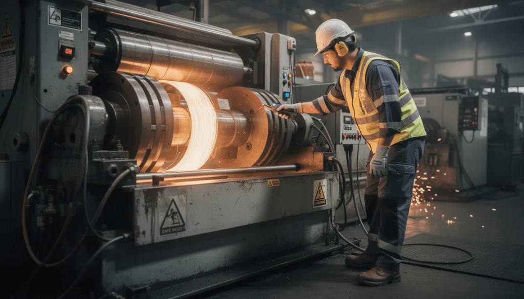
Safety Requirements
- Guarding – All rotating blocks and capstans must have appropriate protective enclosures.
- Emergency stops – Accessible E-stop circuits throughout the line
- Interlocked access – Doors that stop equipment when opened
- Personal protection – Hearing protection in high-noise areas, safety glasses, and appropriate footwear
- Training – Operators must understand safe coil change procedures and threading techniques
Maintaining detailed logs of maintenance activities and drawing process records (speeds, reductions, die life) helps optimize settings and extend both die and machine lifespan. This data also supports troubleshooting when quality issues arise.
With proper operation and maintenance, your wire drawing machine will deliver consistent, high-quality output for years to come.
FAQ – Wire Drawing Machines
This FAQ addresses additional practical questions not fully covered above, focusing on real-world implementation concerns.
Can one wire drawing machine handle both low-carbon and high-carbon steel?
Many modern lines can process both materials, provided they have appropriate die materials, lubrication systems, and control flexibility. However, process parameters must be adjusted—low carbon steel allows higher speeds and larger reductions, while high carbon steel requires more gradual reduction schedules and often slower drawing speeds. In some cases, separate die sets and payoff/coiler setups are recommended to optimize each material without compromising quality or equipment life.
How often should drawing dies be replaced?
Die life depends on material hardness, reduction percentage, drawing speed, and lubrication quality. In a well-optimized steel wire line, tungsten carbide dies might last from several tons to tens of tons of drawn wire before requiring replacement or reconditioning. Plants typically monitor diameter drift and surface finish to schedule replacements before failure occurs. Tracking die life of the product and conditions helps predict replacement needs and maintain spare die inventory.
Is wet drawing always better than dry drawing?
Wet drawing (water or emulsion tank) offers superior cooling and surface finish for fine wire and high speeds, making it essential for many applications. However, dry drawing with solid lubricants remains economical and effective for many medium and large-diameter carbon steel products. The choice depends on wire diameter, required surface quality, production speed, and cost considerations. Dry drawing also simplifies waste handling since there’s no emulsion to filter and maintain.
Can old mechanical wire drawing machines be upgraded?
Many machines from the 1980s–2000s can be retrofitted with modern drives, electronic controls, and new die holders, improving energy efficiency and consistency without replacing the entire mechanical structure. Upgrades typically include PLC-based control systems, variable frequency drives, and improved tension sensors. However, very old frames may limit achievable speeds due to vibration characteristics or bearing capabilities, making full replacement more practical in some cases.
What documentation is needed before ordering a new wire drawing line?
Prepare comprehensive documentation including:
- Materials list (grades, coatings, and surface conditions)
- Coil weights for both the inlet and the finished product
- All inlet rod sizes you plan to process
- Target finish diameters for each product
- Required annual tonnage by product category
- Available plant power (kVA) and voltage specifications
- Layout drawings showing the available installation area and ceiling height
- Integration requirements with existing equipment
This information enables suppliers like Sky Bluer Industries to design an appropriate machine configuration and line layout that meets your specific production requirements without costly modifications later.